Footage Of Our Running Steam Engine

This past Thursday, the gang went over to the New England Wireless & Steam Museum in East Greenwich, Rhode Island to show off the steam engine’s working capabilities.

Everything started off a bit slow; they couldn’t quite get things moving for a bit, and a burst steam line left everyone shaky…

But nevertheless, Don made it happen! It ran for 40 minutes, both in forward and in reverse. It could have kept running for much longer, too!

Here it is:

Marsh Feed Pump and More

We recently acquired a “marsh feed pump” for our steam launch from Chris McMullen, a friend out of New Zealand; he first got the piece from Portsmouth, N.H., so it’s done quite a bit of traveling! Chris is also working on creating an H.M. Co. steam replica. Don has been working on the pump since it came in.

20170404_10421620170404_10420220170329_165258

Meanwhile, Bill has been cutting out the steam launch’s oak stern post, and Bern has been working on the keelson.

20170221_15082220170311_142525

Progress is Slowly Made

Over the past few weeks, the crew has been working tediously to construct the steam ship as precisely as we can. Now that the ribs are curved and attached to the larger vessel, the team had begun shaping the large keel plank.

20170204_11192420170131_120706

After these poor souls’ seemingly endless toil, we were left with a keel plank that, when laid out on the boat, fits on very well! A few imperfections here and there, but that’s for another time.

20170204_15102920170204_151034


Full Steam Ahead!

With the forms laid out and shaped after many hours of trimming to build a smooth hull, it is finally time to actually start building hull #199!

First step is to get the raw oak lumber needed to build the ribs and keel:

rawlumber-copy

The shorter boards are designated for the ribs. The longer board will be used primarily for the keel and false keel.

The raw wood was first cut to the proper size:

rippingribs-copy

And then run through a planer to achieve proper dimensions:

planingribs-copy

Meanwhile Eric is working on a full scale template for the false keel:

cuttingtemplateforkeel-copy

With the ribs properly sized, it’s time to actually steam the ribs and shape onto the forms!

Here’s the steamer we used:

steamer-copy

We used wall paper removal steamers to provide the heat and the ribs were put in for about one hour.

Here’s the first rib being attached:

puttingonfirstrib-copy

firstrib-copy

Steve and Keith are certainly enjoying the first part of the real hull! Either that or someone cracked another stupid joke!

Note the blocks along the edge of the form that are used to keep the rib flush as it cools.

On the second day of forming ribs, we had many hands expediting the process:

manyhandsonrib-copy

I wonder how the piece of wood tastes?

This is certainly a “moment in time” now that we are building hull #199!

Steamboat Building

Work has begun building a section of launch #199. We are building the launch true to HMCo techniques as best we can. The section will be about 2/3 of the length of the 30 foot  launch (frames 7 to 26) – enough to include the engine cooling line underwater.

The first step was to build a lofting table on which the forms for the ribs will be built:

loftingtable-copy

Notice the supreme concentration……

The lofting table was built to allow full size creation of the rib forms.

Using a table of offsets, each rib mold was laid out on the table:

formlayout-copy

All the forms were then combined upside down to form the basis for actually building the boat:

199hullmolds

While the boat hull is being built, the layout of the engine and boiler is under study. The drawing we are working from shows a little detail on the installation:

engineinstall-copy


Unfortunately, some detail is missing on piping and peripherals. So we are reaching out for help from others. One interesting museum near us is the New England Wireless and Steam Museum (www.newsm.org) that actually has a much bigger version of an HMCo steam engine on display that actually runs! See our visit earlier in this blog.


We have also enlisted Chris McMullen from New Zealand as a technical advisor. He is building FROM SCRATCH a copy of our engine and the associated Marsh Pump and is also building a replica of the vessel “Vapor” to put it all in! Amazing!


Here is more information on Chris’s boat:

https://waitematawoodys.com/2014/07/07/chris-mcmullens-herreshoff-steam-launch/

Next up will be more information on our progress!


Checking Out a Running Triple Expansion

The Building 28 gang recently made their way into East Greenwich, R.I. to explore the New England Wireless and Steam Museum, where the Herreshoff triple expansion steam engine is now being shown off.

Their museum visit was given the ultimate treat: the folks at NEWSM ran the engine for the crew!

20161001_10205620161001_102046

Advanced Display

So the display of the triple engine and boiler is complete as standalone pieces but wouldn’t it be great if we could show how they would have been installed in a real boat!

EngineDisplay

Here is a picture of “Vapor” which actually had a similar configuration to ours installed:

vapor
Launch “Vapor”

It just so happens that we have plans for a different hull #199 which was a 30 foot launch that fits the bill and was similar to “Vapor”! Also, Herreshoff has on display in T. F. Green airport in Providence, Rhode Island the vessel “Two Forty” that resembles “Vapor”. The primary difference is that the “Two Forty” displayed is set up for a gasoline engine built around 1937:

Steamboatsmall

(Note the industrious workers inspecting “Two Forty”)!

It’s amazing how narrow these boats are:

HullTopViewsmall

Here’s another shot showing the bow:

TwoFortyBowsmall

The “Crew” made the trip to view “Two Forty” to get a feeling on how these boats were built. In particular, we wanted to study the way the ribs and planking were done:

HullRibssmall

Our new task is to build an actual hull section to display the engine and boiler. We plan to build a full sized section of the hull with part of one side cut out to show the installation.


One interesting note about our field trip was that even though this bunch of guys was crawling all over this boat in the baggage arrival section, the only time anyone seemed to care was when a policeman with a dog (assumed to be a bomb sniffer) walked by! If only actually flying was this easy!

Next up we begin to build the hull!


Time To Heat Things Up


With the engine cleaned and lubricated, I turned my attention to the Type “A” boiler that we had on hand. Unfortunately, we don’t have much information about its beginnings but our records indicate that this type of boiler would have been used with our type engine. The following shows how the boiler might have been installed:

BoilerDrawing


Here is a picture of our boiler as we received it:

Boiler


As you can see, lots of ancillary items are missing but you can get a feeling for how it looked. Water would flow in through the bottom pipes and filled up to the top tube. A coal fire was built under the middle that would boil the water to steam that would then be taken off the top of the upper tube and used to power the engine. The steam coming out would have an oil mist introduced to lubricate the engine. Once the steam was used, it would be condensed then reused in the boiler.

The following shows the stand under construction that was built out of wood but finished to look like metal.

BoilerStandFinal

The round rods would hold the coal fire and the area below would act as the ash pit. The boiler sits on top of the rods:

BoilerOnStand

The completed boiler and engine have now been moved to the Herreshoff display:

EngineDisplay

Next up is exciting news about our display!

Cleaning Things Up – Getting Cranky


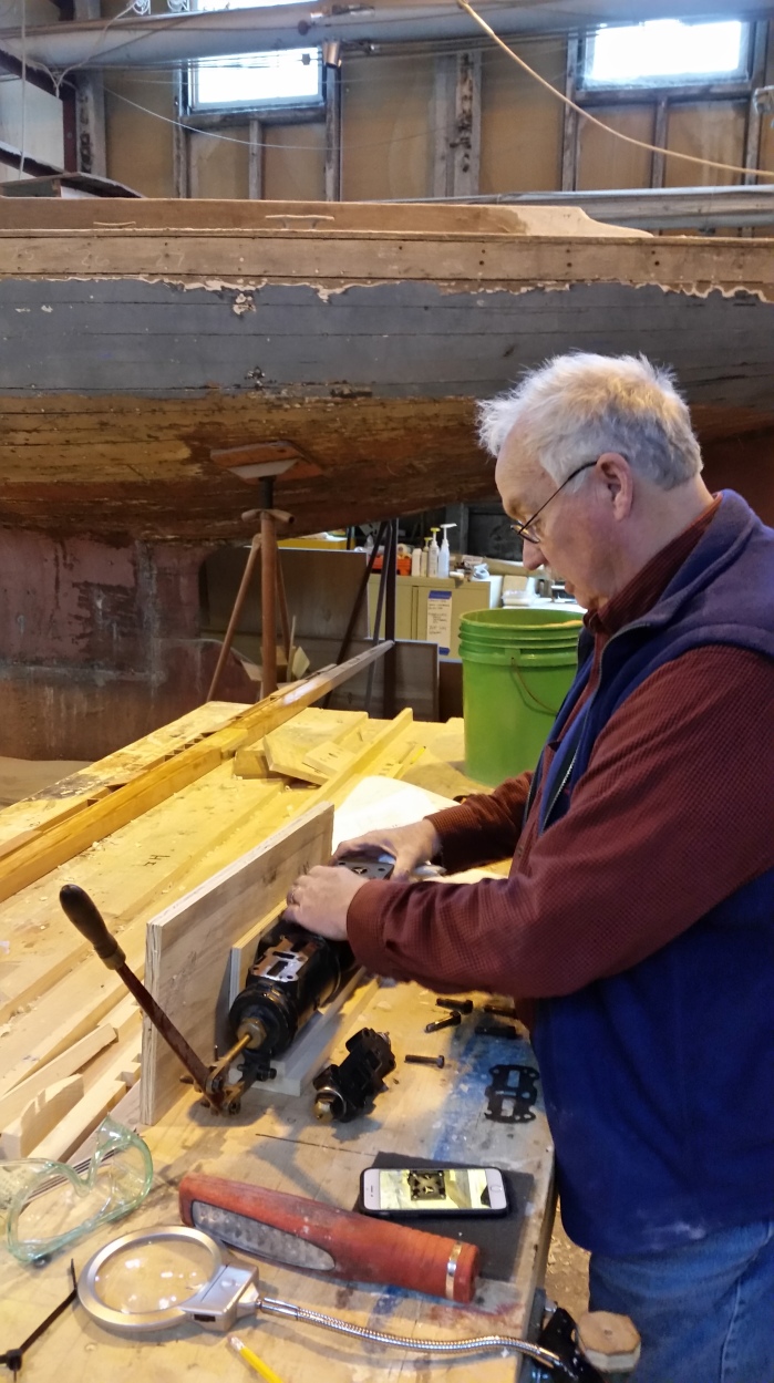
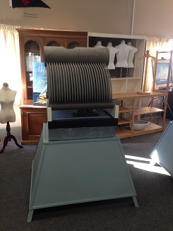
With the engine tucked away in Building 28 at the Museum, the cleaning process began. Where to start? We discussed the options and decided that the best route was to work on getting the engine to rotate if possible and do a comprehensive cleaning without disassembling major components.

I decided to start at the bottom primarily because that area (crankshaft, camshaft, connecting rods etc.) was the dirtiest and key to getting it to rotate.

SteamBottomStart

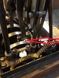
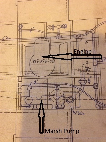
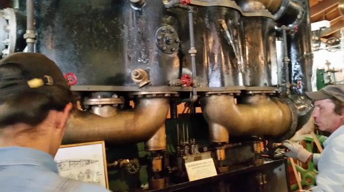
The engine was “wet lubricated” (my term) which means that it had oil in the bottom and the rotation of the engine caused oil to be splashed up into the area of moving parts. If you look at the red arrow in the picture above, you will see a small hole. These are in every rotating piece that needs lubrication and basically allows oil to drop into the bearings. Obviously, the bottom of the engine would have to be enclosed to keep the oil from giving the on-board steam engineer a hot oil bath! Some engines didn’t use the “splash” technique and had oil systems that included a reservoir with a small tube out the bottom that then dripped oil onto the rotating parts (sometimes into holes similar to the above).

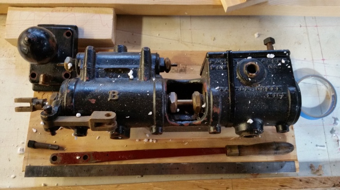
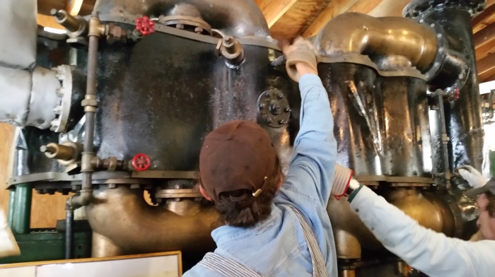
In this engine, someone had put little wooden plugs (much like the end of a chopstick) into most of the lubrication holes. What a great idea that was! It helped keep out nastiness! Unfortunately, the engine had sat so long (after all, she was built in late 1890’s) that it wouldn’t turn. So, I pulled out all the plugs and squirted into the holes a little mystery oil over the period of a few weeks. Then I switched to chain saw oil which has a chemical that sticks to metal better. Lo and behold, after a few more weeks I got the engine to spin a little by putting a long bar across the flywheel connector on the crankshaft! The red arrow in the picture below shows where the flywheel attaches.

SteamFlywheel

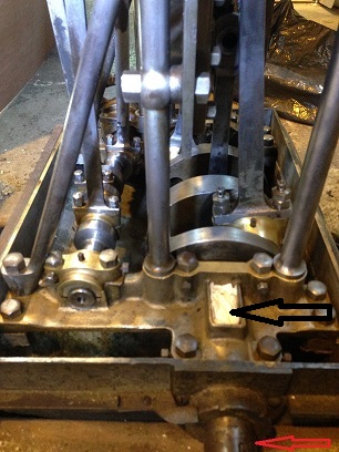
You can also see the little wooden pegs in the bearings. The white paper towel in the small square area just above the flywheel (at the black arrow) is a larger oil container that lubricated the large bearing under it. With continued lubricating and increasingly more rotating effort, I was finally able to get the engine to turn! Success!

While working to get the engine to rotate, I started the cleaning process. I had to be careful not to introduce any foreign objects like metal into the engine so I relied on liquid agents like carburetor cleaner and WD-40 to help clean. I also used 3M Black and Red pads to help with surface rust and dirt. The cleaning was difficult and time consuming with all the tiny areas of the engine. It would have been nice to steam clean the whole engine but that was not even possible since it would potentially harm the engine. So all cleaning was done by hand. But what a beautiful engine!


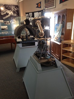
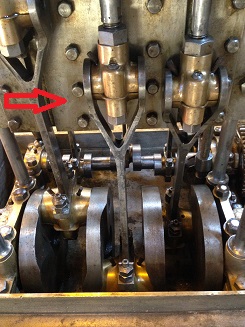
The following picture shows the bottom section of the engine after some cleaning. The red arrow shows the “knuckles” (my term) that connect the crankshaft journals to the pistons above (not in the picture). You can see how nicely the brass cleaned up!

SteamCleanedCrank2

Stay tuned for more news!


Triple Expansion Engine Restoration

In the beginning, there was water. Its primary use was survival of all living creatures. Then, someone discovered fire – how that occurred is open for debate but obviously it happened! Now that fire was available, early humans (they had to have an opposing thumb to lift up a pot!) heated up the water to make coffee (well, that sounds good!). At some point the pot being used (I have no idea who discovered the utensil to hold water over a fire) was covered to speed up the heating of the water. Perhaps by accident, a cover was left on too long and pressure built up and then we had steam!

Now, what to do with this hot, high pressure water vapor? Cooking lobsters leaps to mind but that’s a different discussion. Here’s one possibility – in the first century A.D., Hero of Alexandria invented the aeolipile, or primitive steam turbine:

aolipileLabeled2

Skipping ahead a few years to 1878, Nathanael Greene Herreshoff formed Herreshoff Manufacturing Company. One of his projects was the motor launch “Vapor” built around 1898 which was powered by the triple expansion steam engine.

Leaping ahead to the spring of 2015, a project began that is the “restoration” of a Herreshoff triple expansion steam engine with cylinder bores of 3-1/2”, 5” and 8” and sporting a 4–1/2” stroke.

SteamEngine StartClean

The engine had been residing in the main museum building hidden in the dark recesses near the upcoming Steam Engine display area. While a fairly complete circa 1898 engine, it was in need of some TLC. It was brought up to the building where the Reliance Project (www.therelianceproject.com) is underway. While the steam engine was not part of the original Reliance (she had no power and was perhaps a little heavy for this engine) she is from the same heritage.

SteamEngine 077

SteamEngine 076

Thus, the restoration began to clean up the” little engine that could”. The concept is to bring it to a level that can show the imaginative engineering of Capt. Nat and bring to the public eye the major achievements of the Herreshoff Manufacturing Company in steam engine technology.